


May 10, 2019

Posted by: datacenternews at
06:36 AM
| No Comments
| Add Comment
Post contains 269 words, total size 3 kb.
March 14, 2019
Researchers have made great progress in optical devices. The output power of laser, linewidth, stability and noise, as well as the bandwidth of photodetectors, power capacity and common mode rejection ratio have been greatly improved. Microwave electronic devices have also been greatly improved. Then, the coherent optical communication technology has gradually become an important capacity-lifting solution for the current 100G line-side.
Market Demand for Coherent Optical Communication
One of the biggest drivers of growth in the current communications market is the transition from 10G to 100G in the metro, core and Data Center Interconnect (DCI) sectors.
With the explosive growth of information generated by the use of communication technologies such as video conferencing and the spread of the Internet, the market has proposed higher transmission performance requirements for the physical layer that is the basis of the entire communication system.

In terms of digital communication, how to expand the capacity of C-band amplifiers, overcome the deterioration of fiber dispersion effects, and increase the capacity and range of free-space transmission have become important considerations for researchers; in analog communication, sensitivity and dynamic range are key parameters of systems.
Driven by strong demand, large-scale DWDM systems are gradually depleting their wavelength resources, and the efficiency of Time-Division Multiplexing (TDM) systems through compressed optical pulses also has a large technical bottleneck. People began to consider replacing the original Wavelength Division Multiplexing (WDM) system with a coherent optical communication system.
Advantages of Coherent Optical Modules
The coherent optical communication system modulates the signal to the optical carrier by adjusting the amplitude, phase and frequency by means of external light modulation (such as DP-QPSK) at the transmitting end.
Compared with the traditional direct detection system, coherent detection can obtain more signal information through the signal light and the beat frequency of the local oscillator; after the signal reaches the receiving end, it uses high-speed Digital Signal Processing (DSP) technology to perform front-end processing such as equalization. The optical mixer and the optical signal generated by the local oscillator are coherently mixed to realize signal reconstruction and distortion compensation.

Coherent optics can be used in both 100G and 400G applications, primarily because it enables service providers to send more data over existing fiber, reducing the cost and complexity of network upgrades for bandwidth expansion.
- Coherent detection combined with DSP technology:
- Cleared barriers to traditional coherent reception
- Compensate for various transmission impairments in the electrical domain, simplifying transmission links
- Make high-order modulation formats and polarization states possible
- At the same time, the application of high-order modulation formats enables coherent optical communication to have higher single-wavelength channel spectrum utilization compared to traditional system systems.
Coherent receivers have no special requirements for fiber channel, so coherent optical communication can use already laid fiber lines. With the aid of digital signal processing algorithms, coherent receivers compensate for signal distortion caused by fiber dispersion, polarization mode dispersion, and carrier phase noise at a very small cost. - A coherent receiver is about 20 dB more sensitive than a normal receiver, so the distance that is not relayed in the transmission system becomes longer, which reduces the number of amplifications in the transmitted light path.
Based on the above reasons, coherent optical communication can reduce the cost of optical fiber erection for long-distance transmission, simplify optical path amplification and compensation design, and become the main application technology of current long-distance transmission network.
Application Scenarios of Coherent Optical Modules
At present, the coherent optical communication is mainly used on the line side of the backbone network and the metropolitan area network, and belongs to the technical research field of DWDM long-distance transmission. In the application scenarios of the metropolitan area network and the core network with distance more than 80km, the coherent optical communication features good performance of Optical Signal-to-Noise Ratio (OSNR), sensitivity, dispersion tolerance and so on.

WDM System
The operating wavelength range is C-band (1530nm to 1565nm), and the fiber type is G.652D (prefered) or G.655. The key performance index is OSNR.
Error correction coding technology can jump out of the limitations of the physical layer of transmission, and compensate for all physical transmission impairments at the logic layer, especially the effects of nonlinear effects.

5G Middlehaul/Backhaul Network
In the 5G middlehaul scenario, 100G/200G DWDM system will be deployed, and the 100G CFP-DCO and 200G CFP2-DCO optical module can be used to implement the 80km scene application; the 400G DCO product is applied in the 5G backhaul scenario with distance less than 200km.
DCI
Whether the coherent communication will be used in the DCI field of 40km to 80km depends mainly depends on the commercial cost performance and whether the market capacity is large enough.
At the current 100G rate, products such as 100G ER with EML modulation are sufficient for the use; the 100G CFP-DCO ZR series will appear in the future.

The OIF organization is developing a 400ZR specification that uses a combination of DWDM and coherent technology.
Andrew Schmitt, principal analyst at Cignal AI, said: "Coherent 400G will limit the development of existing 200G and 100G technologies by 2020, and new devices will maximize optical capacity without relying on coverage." Foreseeable Yes, more and more 400ZR products will enter the market.
Summary
The coherent optical communication system is a more advanced and complex optical transmission system suitable for longer distance and larger capacity information transmission.
At present, coherent modules with the CFP form-factor are bulky and consume large power. Compact coherent modules will replace existing coherent products. The innovation of semiconductor technology and the improvement of chip technology will greatly promote the replacement of 400G coherent products.
In recent years, Gigalight, a global optical interconnect innovator, has increased its research and development of coherent modules and has achieved a series of achievements. In the next few years, it will strengthen cooperation with the industry and jointly promote the progress of related industries.
Source: Analysis of the Current Coherent Optical Module Market
Posted by: datacenternews at
09:52 AM
| No Comments
| Add Comment
Post contains 990 words, total size 9 kb.
March 08, 2019
1. What Are the Benefits of Using 200G AOCs?
- To address the need for high-density, high-speed networking solutions
- To support a variety of next-generation of Ethernet applications
- The 200G AOCs are crucial to enable hyperscale data centers, service providers and enterprises to meet growing bandwidth demands
- Backward plug compatible with existing 100G-based systems and flexible port bandwidth for system design
2. What 200G AOCs Are Available on the Market?
Currently, there are only a few suppliers of 200G AOCs on the market, for example, the Gigalight company — a leader in the AOC industry. Gigalight offers a full range of 200G AOCs in both QSFP-DD and QSFP56 form-factors. The Gigalight 200G AOC product line includes 200G QSFP-DD AOC, 200G QSFP-DD to 2x 100G QSFP28 AOC, 200G QSFP-DD to 4x 50G QSFP28 AOC, 200G QSFP56 AOC, 200G QSFP56 to 2x 100G QSFP56 AOC, 200G QSFP56 to 4x 50G SFP56 AOC. All of these cable assemblies are compliant to IEEE standards and industry Multi-Source Agreements (MSAs).

Table 1: The Maximum Data Rates of Gigalight 200G AOCs
Note:
The QSFP-DD stands for a "Quad Small Form-factor Pluggable–Double Density". The QSFP-DD connector also has 8 electrical lanes similar to the QSFP form-factor, but the second row of electrical contacts has been added to the QSFP connector in order to increase the number of high-speed electrical lanes from 4 (in a QSFP) to 8 (in a QSFP-DD).
The QSFP56 stands for "Quad Small Form-factor Pluggable 56 ('56' refers to the max data rate 56Gb/s each electrical interface can handle)". The QSFP56 form-factor is a solution for 200G applications. It's a pluggable form-factor that has the same size as QSFP.
3. Can QSFP56 AOC Support QSFP-DD AOC Ports or Can QSFP-DD AOC Support QSFP56 AOC Ports?
Yes. The QSFP56 is a pluggable form-factor that has the same size as QSFP. The QSFP-DD assemblies are backward compatible with existing QSFP, so your 200G QSFP56 AOC can be used in the 200G QSFP-DD AOC system ports. Your 200G QSFP-DD AOC also can be used in the 200G QSFP56 AOC system ports.
4. What Is the Maximum Distance of 200G AOCs?
For Gigalight's 200G AOCs, a max length of 100m is supported for both QSFP-DD AOCs and QSFP56 AOCs using OM4 MMF.
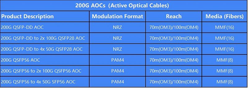
Table 2: The Maximum Distances of Gigalight 200G AOCs
5. What Industry Standards Are Associated with 200G AOCs?
The QSFP-DD series AOCs are compliant with the QSFP-DD MSA while the QSFP56 series AOCs are compliant with the QSFP MSA.
6. What Is the Maximum Power Consumption of 200G AOCs?
The maximum power consumption of 200G QSFP-DD AOCs (based on NRZ) is 4w per end while that of 200G QSFP56 AOCs (based on PAM4) is 7w per end.
In general, higher power consumption levels are associated with higher data rates and longer reach.
7. Where Are 200G AOC Used?
The 200G AOCs are suitable for short distances and offer a cost-effective solution to connect within racks and across adjacent racks. While the 200G Direct Attach Cables (DAC) are a low-cost solution for 200GE high-speed interconnects within the reach up to 3 meters only, the 200G AOCs pick it up from there and can reach up to 100 meters. The 200G AOCs are widely used in High-Performance Computing (HPC) and recently became more popular in hyperscale data centers, enterprise and storage systems.
Originally article: 7 Frequently Asked Questions About 200G Active Optical Cables (AOCs)
Posted by: datacenternews at
08:11 AM
| No Comments
| Add Comment
Post contains 575 words, total size 5 kb.
March 07, 2019

The Market Situation of AOC
Today’s hyperscale data centers and High-Performance Computing (HPC) markets require low-cost solutions for high-performance AOCs for the large-scale adoption of 200G and 400G data rates.
According to a recent report from LightCounting, the multi-mode AOC market will be experiencing significant growth over the next five years in the HPC and large-scale data center applications.
However, the market for 100G AOC is continually growing in the HPC and large-scale data center applications now, and it is still too early to adopt 400G AOC owing to cost and others so that the adoption of 200G AOC is expected to grow in the next years.
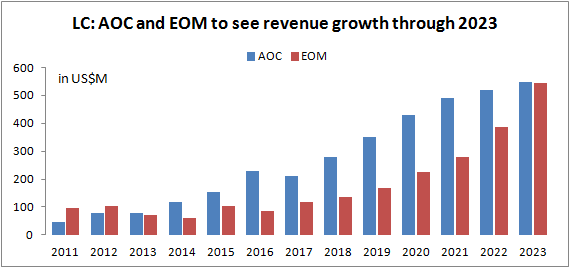
AOC and EOM to see revenue growth through 2023 (Source: LightCounting)
In the 200G AOC market, the 200G QSFP-DD AOC is a kind of parallel transceiver optics assembly. It will be the huge potential market and it is possible to replace copper technology in HPC and data center, the reasons include form factor, cost and so on. Next, we will explore them together.
Why Is 200G QSFP-DD AOC More Likely to Be Popular?
The 200G QSFP-DD AOC is a kind of 200G AOC that adopts the QSFP-DD form factor.
QSFP-DD is an eight-channel electrical interface with an additional row of contacts. It is being developed by the QSFP-DD MSA as a key part of the industry’s effort to enable high-speed solutions. The 200G QSFP-DD AOC meets the requirements of QSFP-DD MSA specification.
The QSFP-DD modules are similar to current QSFP. The systems designed with QSFP-DD modules can be backward compatible, allowing them to support existing QSFP modules and provide flexibility for end users and system designers. The 200G QSFP-DD AOC is convenient for end users and system designers.
The Introduction of Gigalight 200G QSFP-DD AOC
Gigalight is one of the rare providers for 200G QSFP-DD AOC. Its 200G QSFP-DD AOC is driving from its innovative optical packaging and the key manufacturing technologies enable scalability, reduced power consumption, increased reliability, and superior module performance for optical communications.
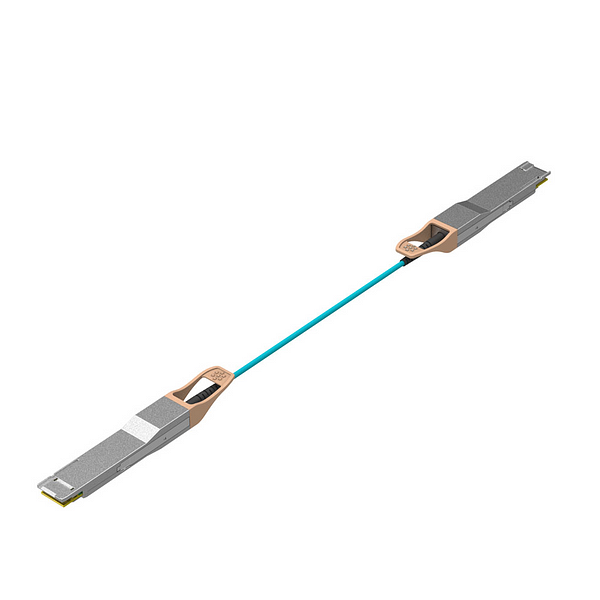
Gigalight 200G QSFP-DD AOC
Features of Gigalight 200G QSFP-DD AOC
- 8 channels full-duplex 850nm parallel active optical cable
- Transmission data rate up to 25.78Gbps per channel with integrated CDR
- Hot-pluggable QSFP-DD form-factor connectors
- Low power consumption < 4W per end
- Operating case temperature range 0°C to +70°C
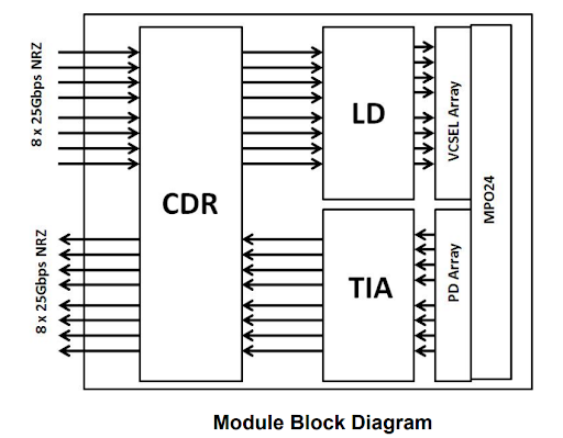
The module block diagram of Gigalight 200G QSFP-DD AOC
Gigalight 200G QSFP-DD AOC adopts self-developed COB (Chip on Board) high-precision technology. The cost of the product is lower and the volume is smaller, which can provide a new generation solution with low cost, low power consumption, high density and high speed for the data center.
Originally article: An Overview of 200G QSFP-DD AOC
Posted by: datacenternews at
06:11 AM
| No Comments
| Add Comment
Post contains 449 words, total size 4 kb.
March 05, 2019
According to data disclosed by Google, Facebook, etc., the internal traffic of these Internet giant data centers is increasing by nearly 100% every year. Currently, some Internet giants deploying 100G earlier have begun to seek higher-speed solutions, and the choice of next-generation data centers has become A topic that everyone is enthusiastic about.
The 400G Ethernet standard is preceded by the 200G Ethernet standard, which may reflect the industry’s mindset—more optimistic about 400G, or 200G is just a transition solution for 400G.
But directly from 100G to 400G is actually not very scientific.
- First of all, from the data center side, we need to rebuild the ultra-large-scale data center and define a new specification architecture. The requirements for rack power in the 400G era switch will be quite high, and the traditional air-cooling heat dissipation is more difficult.
- Furthermore, the 400G data center will use PAM4 technology, and the PAM4 technology will make the system less transparent and difficult to manage. The traditional NRZ technology together with the parallel technology can make the data center easy to manage.
In order to more flexibly adapt to the needs of the future data center and achieve a perfect transition to the 400G data center, Gigalight recently completed a low-cost data center internal parallel optical interconnection solution based on 200G NRZ transmission. This paper mainly compares 200G NRZ—Two parallel technologies in the solution, and two products as an example for simple analysis.
Fiber Parallel Solution—Is It Single- or Multi-Mode?
The traditional parallel optical module products are mainly based on optical interconnect technology of multimode fiber, and have the advantages of high bandwidth, low loss, no crosstalk and matching and electromagnetic compatibility problems. They have gradually replaced copper-based electrical interconnection products and are used in cabinets. High-speed interconnection between the boards, the connection distance is up to 300 meters under the OM3 fiber.
At the same time, in order to apply to longer-distance transmission solutions, Parallel Single-Mode (PSM) optical modules have emerged, mainly using FP lasers to transmit 2km in single-mode fiber and DFB to transmit 10km applications, which is more difficult than multi-mode interconnection technology.
Data center cabling is a very complicated problem. The choice of multimode fiber or single-mode fiber has been the subject of heated discussion in the industry. There are also choices in major data centers. For example, in the 100G era, Facebook chooses single mode, Google chooses both multimode and single mode. At the same time, BAT (Baidu, Alibaba, Tencent) chooses multimode. From the perspective of cost, multimode fiber is expensive and multimode optical module is cheap. Single mode fiber is cheap and single mode optical module is expensive. Therefore, it is easy to combine the cost of fiber and optical module to obtain the relationship between distance and cost. Taking the 100G solution as an example, the cost advantage of a multimode solution is very obvious when the fiber distance is within 100 meters.
The parallel technology route is characterized in that each pair of multimode fibers respectively carries one optical signal. At present, IEEE’s 400G SR16 standard is a 16x 25G parallel solution, which requires 16 pairs of multimode fiber. It is far more than the 12-core MPO widely used in the 100G era, which will lead to a significant increase in cost; more importantly, multimode optical modules rely on The low-cost VCSEL optical chip solution, 2020, is likely to still require more than 12-core MPO’s 8-pair multimode fiber. The 400G SR4 that the existing 12-pin MPO can accommodate seems to be in the foreseeable future.
Therefore, in 2020, if there is no open and standardized multi-mode wavelength multiplexing technology (such as SWDM technology), low-cost VCSEL 100G technology can not achieve breakthrough, 400G multi-mode fiber solution cost advantage will no longer be obvious, single-mode fiber It may become mainstream in large-scale data centers, and short- and medium-range single-mode parallel solutions will be a cost-effective alternative to multi-mode parallel solutions.
——Yang Zhihua, "Top Ten Hotspots of Data Center Network Technology in 2020"
200G PSM8 vs. 200G SR8
Based on Gigalight’s unique PSM series product line, Gigalight recently released a new product—200G QSFP-DD PSM8, a high-speed product of single-mode parallel technology.
To achieve long-distance transmission, single-mode fiber with low dispersion loss must be used. To achieve high coupling efficiency between single-mode fiber and semiconductor, it is necessary to shape the light field emitted by the semiconductor laser to maximize the incident light field and the intrinsic optical field of the fiber.
And the 200G QSFP-DD SR8 uses an 8-channel 850nm VCSEL array that complies with the 100GBASE-SR4 protocol standard. The 200G QSFP-DD SR8 is a multimode parallel product. With the traditional VCSEL advantage platform, Gigalight uses a simple, efficient and reliable fiber coupling process technology to add a 45° prism between the laser and the fiber. The special material treatment of the fiber surface increases the coupling efficiency of the fiber to over 80%.
The two products are similar in that they belong to the optical modules in the 200G data center solution, and all use the QSFP-DD package, which can use the 16-core MTP.
The advantage of QSFP-DD is that the 1U panel can achieve a density of 36x 200G/400G, and it is forward- and backward compatible with QSFP, and is compatible with existing QSFP28 optical modules and AOC/DAC.
The main difference is that the 200G QSFP-DD PSM8 adopts an 8-way 1310nm single-mode fiber parallel solution with a transmission distance of up to 10km. The 200G QSFP-DD SR8 adopts a multi-mode fiber parallel solution and can travel over the OM4 fiber link. Up to 100m.
Summary
The multi-mode parallel solution is the core of the current data center development, and the transmission distance between the switch and the core switch is just within the scope of the multi-mode fiber.
Corning has introduced OM5 fiber in the past few years, but it has not caused the expected market reaction. The SWDM short-range wavelength division multiplexing scheme is only promoted by a few manufacturers—it is indeed lacking in the market.
In the near future, if a general enterprise data center wants to continue to use standard-certified solutions and reduce the cost of optical components, you can choose multi-mode parallel optics—after all, SMBs do not need as large a capacity as 400G.
However, if it is in the construction and deployment process of a very large-scale data center, especially considering the scalability of the system and the flexibility of the system, we should probably consider the single-mode parallel solution.
In the eyes of some people of insight, the single-mode parallel solution increases the number of fiber cores, but overall reduces the maintenance complexity, is easier to manage, and is easier to upgrade from 100G to 400G later. Without increasing fiber resources, the current 100G CWDM4 based on wavelength division multiplexing can only evolve to 200G FR4, and 100G PSM4 can be upgraded to 400G DR4).
——Li Mofei, "Review of Data Center: Cost Technology is Concise and Reconfigurable"
In general, the technology roadmap for major switch and transceiver vendors shows a very clear and simple migration path for customers deploying parallel optics. So when optics are available and migrated from 100G to 200G or 400G, their fiber infrastructure still exists and no upgrades are required.
Reliability, product life and maintenance costs are all interrelated. The parallel single-mode solution represented by 200G QSFP-DD PSM8 in total cost should be the cabling guide for large-scale data centers in the future.
Originally article: Comparison of Two Parallel Technologies in 200G Optical Modules
Posted by: datacenternews at
07:06 AM
| No Comments
| Add Comment
Post contains 1256 words, total size 10 kb.
February 22, 2019
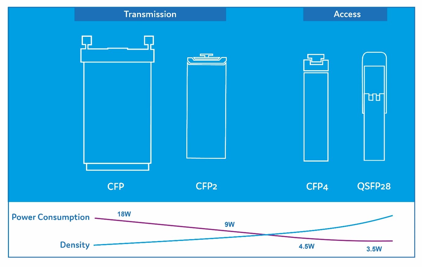
There are three criteria for a successful form-factor: small size, low power consumption, and interoperability between all systems vendors. As we all know, the SFP/SFP+ and QSFP+/QSFP28 are successful form-factors for 1G/10G and 40G/100G networks. In fact, for 100G networks, there are 4 different form-factors: CFP, CFP2, CFP4, and QSFP28.
100G form-factors: CFP vs. CFP2 vs. CFP4 vs. QSFP28
100G
The transmission departments in telecommunication networks need a pluggable transceiver able to cover long reach also using some dedicated technologies such as Coherent detection, while data centers need a small form-factor with the lowest power consumption and the lowest cost per unit due to their application is for short reach only (max 2km generally).
During the first instances of the 100G transceivers, the CFP form-factor was preferred because it was impossible to make a transceiver less than 12W power consumption, even for intermediate reach. Once the technology and components availability were better, it was then feasible to CFP2, and then CFP4. Still today, the Coherent technology for 100G and 200G is only available on CFP and CFP2 form-factors.
In parallel, the GAFA (Google, Apple, Facebook, and Amazon) with their phenomenal need for additional data center capacity, have pushed the QSFP28 form-factor for various short reach applications such as DAC, AOC, SR4, PSM4, and CWDM4.
Today, with the technology maturity and QSFP28 wide-adoption, most of the 100G applications are available on QSFP28 form-factor, with some exceptions for reach more than 40km, including Coherent detection.
400G
For 400G bit-rate, some essentials interrogations must be raised before going deeper into the subject:
- Who need the 400G transceivers?
- For which application?
- How about technology maturity?
- Any interoperability with former form-factors?
Following the market situation, 400G is a priority for the intra-connections in large data centers and at a lower scale for the transmission department in telecommunication networks. Because the 400G bit-rate requires PAM4 modulation, the reach is becoming more and more challenging and is limited to a few kilometers only. Longer reach will require Coherent detection technology and/or amplification, dispersion compensation, etc.
Again, we will observe a similar scenario: for 400G networks, a dedicated form-factor for the data center intra-connection (Intra-DC) and another one for transmission. However, thankfully it seems that "intermediate†form-factors won’t happen for 400G.
Intra-DC
400G is coming with 2 form-factors for Intra-DC: QSFP56-DD (QSFP-DD for QSFP Double Density) and OSFP (Octal SFP). Both form-factors are running 8 lanes of 50G PAM4 on the electrical side while the optical side can be either 8 lasers of 50G PAM4 or 4 lasers of 100G PAM4. In the 4-laser design, a "gearbox†is added to convert the PAM4 electrical signal from 8x50G to 4x100G.
The QSFP-DD is defined by the QSFP-DD MSA while the OSFP is defined by the OSFP MSA. They are similar but have three key differences:
- OSFP allows more power (15W) than QSFP-DD (12W) so that the OSFP allows an early adoption because it’s easier to release a technology designed for 15W than 12W.
- QSFP-DD port is backward compatible with QSFP including 40G QSFP+, 100G QSFP28, and 200G QSFP56, while OSFP port requires a QSFP to OSFP adapter.
- OSFP integrates thermal management directly into the form factor, but QSFP-DD does not.
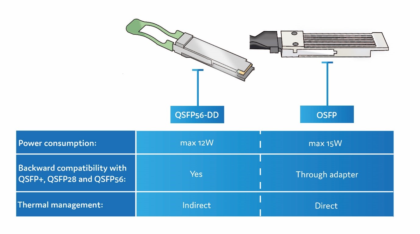
400G form-factors: QSFP56-DD vs. OSFP
Both QSFP-DD and OSFP are designed for intra-DC applications including DAC, AOC and optical connection up to 2km. Additional variants will come for other applications such as Data Center Interconnect (DCI) with longer reach and other technology like DWDM super channel.
Transmission
The CFP8 form-factor, defined by the CFP MSA, is radically different compared to QSFP-DD and OSFP as:
- It allows up 24W power consumption.
- It has 16x25G NRZ on the electrical side instead of 8x50G PAM4 for QSFP-DD and OSFP.
- It has an MDIO management interface instead of I2C for QSFP-DD and OSFP.
With its large space and max 24W power consumption, the CFP8 is intended for transmission application. Available in an initial version of 10km, it has 16 electrical lanes of 25G NRZ which are converted to 8 lanes of 50G PAM4.
However, other variants are coming for longer reach, including Coherent detection technology. A version called CFP8 ZR (80km) will come at a later stage but it also opens the door for a CFP8 800G! By using the 16 electrical lanes and apply a 50Gbps PAM4 signal, it is feasible to reach 800G; then adding a DSP, Coherent detection and multiplexing lasers will enable the optical transmission. Clearly, this is not for today yet.
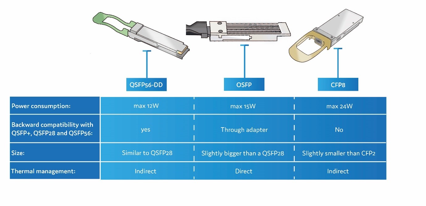
400G form-factors: QSFP56-DD vs. OSFP vs. CFP8
For 400G applications, others form-factors than the one listed above are also available, but for dedicated applications. We can list the COBO (Consortium for On-Board Optics) and the CDFP for cable application enabling 16 electrical lanes of 25Gbps.
Related article: QSFP-DD Might Be the Mainstream Form-factor of 400G Optical Transceivers.
Originally published at QSFP-DD, OSFP, and CFP8: Which Is the Best for 400G?.
Posted by: datacenternews at
07:14 AM
| No Comments
| Add Comment
Post contains 823 words, total size 7 kb.
February 19, 2019
Time to enter 2019, when 400G has become a hot topic in the optical communications industry, the world’s leading optical transceiver manufacturers have launched their own 400G optical modules. When we list the form-factors of these manufacturers’ 400G optical modules (as shown in the figure below), we found that all the manufacturers except the Finisar (acquired by II-VI) have adopted the QSFP-DD form-factor — the market seems to have recognized QSFP-DD as the first choice for form-factors of 400G optical modules, though some manufacturers have also introduced 400G optical modules with OSFP and CFP8 form-factors.

400G Form-factors of Mainstream Optical Transceivers Manufacturers
Tips: QSFP-DD is a high-speed pluggable module form-factor defined by the QSFP-DD MSA group.
"The QSFP-DD MSA group has defined the next generation, high-density, high-speed pluggable module form factor that addresses the industry need for high-density, high-speed networking solutions in a backward compatible form factor. The QSFP-DD Specification has been developed and refined by many companies within the QSFP-DD MSA group and released to the public.â€
Why do mainstream manufacturers choose the QSFP-DD form-factor? Does this mean that the future 400G optical modules will be based on QSFP-DD? In order to clarify these issues, let us first look at the history of QSFP-DD.
History of QSFP-DD
March 21, 2016 — The QSFP-DD MSA group announced a plan to develop high-speed, double-density quad small form factor pluggable interfaces.
September 19, 2016 — The QSFP-DD MSA group announced the release of preliminary hardware specifications, including drawings, for the new QSFP-DD form factor.
March 13, 2017 — The QSFP-DD MSA group released a specification for the new QSFP-DD form factor.
September 19, 2017 — The QSFP-DD MSA group released an updated 3.0 Hardware specification for the new QSFP-DD form factor.
March 13, 2018 — The QSFP-DD MSA group released QSFP-DD thermal white paper to address how the thermal performance of the QSFP-DD module is evaluated for use in a high-performance data center environment.
August 30, 2018 — The QSFP-DD MSA group announced the success of their mechanical plug fest.
September 18, 2018 — The QSFP-DD MSA group announced the release of an updated 4.0 Hardware specification for the QSFP-DD form factor. By this time, the QSFP-DD MSA is relatively complete, and the QSFP-DD optics of the leading optical transceiver manufacturers are also listed in this period. For example, Gigalight, the world’s leading innovator of optical interconnect design, has introduced 200G optical interconnect solutions for large-scale data centers from 100G to 400G — 200G QSFP-DD SR8 and 200G QSFP-DD AOC.
In summary, from the beginning of 2016 to the end of 2018, the birth of QSFP-DD has matured for nearly three years. During this period, the members of the QSFP-DD MSA group have also increased from the original 13 promoters to the current 14 promoters (3 companies were acquired, so only 11 were actually left) and 52 contributors.
The changes in the promoters of the QSFP-DD MSA group during this period also verified an old saying: the hero of the situation — II-VI acquired the old optical transceiver manufacturer Finisar; Broadcom acquired Brocade; Lumentum acquired Oclaro; Cisco also completed the acquisition of Luxtera recently. After so many acquisitions, let’s take a look at the big companies left. There are chip providers such as Broadcom (Avago uses Broadcom as the brand name after the acquisition of Broadcom), equipment vendors such as Cisco and Huawei, device providers such as Lumentum, optical transceiver manufacturers such as Foxconn Interconnect Technology, accessories manufacturers such as Molex and TE Connectivity, and so on, covering the entire communications industry.
Why are so many big companies working together to promote QSFP-DD? Let us find the reasons together now.
Why QSFP-DD
A successful form factor must support the entire set of media and transceiver types prevalent in the networking industry. For media this includes passive Direct Attached Copper cables (DAC), Multi-Mode Fibers (MMF) and Single-Mode Fibers (SMF). For transceivers and active copper or active optical cable assemblies, this includes those defined by Ethernet, Fibre Channel, and InfiniBand for 100 Gb/s, 200 Gb/s and 400 Gb/s. In addition, port density must not be compromised from that of current practice. Further, backward compatibility with the popular QSFP form factor is essential for industry adoption.
QSFP-DD, Quad Small Form-factor Pluggable Double-Density, is a new module and cage/connector system similar to current QSFP, but with an additional row of contacts providing for an eight lane electrical interface. The term "Double-Density†refers to the doubling of the number of high-speed electrical interfaces that the module supports compared to the regular QSFP28 module. The connector specification is ready for the new PAM4 electrical modulation format that supports 50Gb/s that provides another doubling of speed resulting is a 4x increased in port speed for the QSFP-DD compared to the QSFP28 module.

The Diagram of QSFP-DD Module and Host Interface
Next, we will analyze the features of QSFP-DD one by one.
Features and Benefits of QSFP-DD
QSFP-DD expands on the QSFP pluggable form factor, a widely adopted four-lane electrical interface.
QSFP-DD is with 2×1 stacked integrated cage/connector. Due to industry need, most pluggable form factors eventually see developed a two-high stacked cage-connector system in addition to a one-high cage connector system. Often the one-high system is included in the initial MSA specification and the two-high is left to independent individual suppliers. To serve better the industry, the QSFP-DD MSA Group chose to develop concurrently both the one-high and the two-high cage-connector systems.
SMT connector and 1xN cage, Cage design optimizations and module case optimizations enable thermal support of at least 12W per module. The QSFP-DD Specification defines power classes up to 14W as well as a >14W class. Due to innovative thermal management techniques used in the module and cage designs, QSFP-DD modules support power levels of at least 12W in a typical system design. The extensive knowledge and experience of system design with QSFP family form factors enables innovative systems solutions that could extend beyond that range. Thermal management features needed for the higher power consumption classes are relaxed for the lower power classes to avoid unnecessary costs.
QSFP-DD electrical interfaces employs eight lanes that operate up to 25Gb/s NRZ modulation or 50Gb/s PAM4 modulation, providing solutions up to 200Gb/s or 400Gb/s aggregate. QSFP-DD can enable up to 14.4Tb/s aggregate bandwidth in a single switch slot. By quadrupling aggregate switch bandwidth while maintaining port density, QSFP-DD can support continuing growth in network bandwidth demand and datacenter traffic.
Before the emergence of QSFP-DD, the most popular interfaces in the networking industry consisted of single (SFP/SFP+) or quad lanes (QSFP+/QSFP2![]() . However, to accommodate expected demand for data bandwidth or channel capacity, eight lane interfaces are being defined in venues such as Ethernet. The currently available form factors that support eight lane interfaces do not have all the desired features or density necessary to support the next generation systems that plan to implement these higher rate interfaces. Thus, the QSFP-DD MSA group extended and defined QSFP-DD based on QSFP (QSFP+/QSFP2
. However, to accommodate expected demand for data bandwidth or channel capacity, eight lane interfaces are being defined in venues such as Ethernet. The currently available form factors that support eight lane interfaces do not have all the desired features or density necessary to support the next generation systems that plan to implement these higher rate interfaces. Thus, the QSFP-DD MSA group extended and defined QSFP-DD based on QSFP (QSFP+/QSFP2![]() .
.
QSFP-DD vs. QSFP (QSFP+/QSFP2
- The new QSFP-DD interface expands on the QSFP pluggable form factor, a widely adopted four-lane electrical interface used across Ethernet switches that enables interconnection between switches or to servers. QSFP’s four electrical lanes operate at 10Gb/s or 25Gb/s, providing solutions for 40Gb/s or 100Gb/s aggregate. The new QSFP-DD pluggable form factor’s electrical interfaces employ eight lanes that operate up to 25Gb/s NRZ modulation or 50Gb/s PAM4 modulation, providing solutions up to 200Gb/s or 400Gb/s aggregate. This can enable up to 14.4Tb/s aggregate bandwidth in a single switch slot and address rapid datacenter traffic growth.
- Systems designed with QSFP-DD modules are backwards compatible, allowing them to support existing QSFP modules and provide flexibility for end users and system designers. Backwards compatibility is critically important to the industry. Since ASICs are designed to support multiple interface rates, it is critically important that the system can take advantage of this. End users can take advantage of the newer ASIC and system products with lower port costs and are able plug in a wide range of currently available QSFP modules to support their desired media and reach without needing to have separate system products. This greatly decreases the risks associated with implementing new equipment. System designers can build common products that support a multiple of pluggable variants while leveraging known technologies and designs. Module designers do not need to port their lower rate designs into new non-backwards compatible form factors lowering their overall costs. The economy of scale achieved due to backwards compatibility make it highly desirable.
- The system port densities are identical between QSFP-DD and QSFP28 module specifications. However, since each QSFP-DD port can accommodate 8 lanes instead of 4, QSFP-DD doubles the number of ASIC ports it supports for existing interfaces such as CAUI-4.
- The mechanical interface for QSFP-DD on the host board is slightly deeper than for QSFP28 to accommodate the extra row of contacts. The height and width are identical to the QSFP form factor enabling system designers to achieve identical system port count densities for QSFP28 or QSFP-DD based designs. You can plug any current QSFP or QSFP28 module into the QSFP-DD 1×1 or the 2×1 cage/connector combinations.
In summary, QSFP-DD is a little longer than QSFP+/QSFP28 but the port density is the same, and the bandwidth is increased to 10 times or 4 times of the latter, and it is backwards compatible, which means customers can skip the QSFP system and directly deploys the QSFP-DD system, which greatly reduces the equipment costs.
At the beginning of this article, we mentioned that some optical transceiver manufacturers have also introduced 400G optical modules with OSFP and CFP8 form-factors. Let’s compare QSFP-DD and OSFP, QSFP-DD and CFP8 to see how they differ.

QSFP-DD vs. OSFP vs. CFP8
QSFP-DD vs. OSFP
First, let’s take a look at OSFP first. Not long ago (January 16, 2019), OSFP MSA released version 2.0. According to its description, the OSFP is a new pluggable form factor with eight high speed electrical lanes that will initially support 400Gb/s (8x50G). It is slightly wider and deeper than the QSFP but it still supports 36 OSFP ports per 1U front panel, enabling 14.4Tb/s per 1U.
Tips: In the latest release of OSFP MSA, OSFP already supports 800Gb/s, which may be the reason why OSFP is also one of the popular 400G form-factors.
- Size — According to the previous introduction, OSFP seems to have little difference from QSFP-DD, just "slightly wider and longer†than QSFP-DD. However, after comparing their specific size values, we found that the difference is not just a little bit. The width, length and thickness of QSFP-DD are 18.35mm, 89.4mm and 8.5mm, while those of OSFP are 22.58mm, 107.8mm and 13.0mm. If the module is roughly calculated as a cuboid, the volume of the OSFP could be more than twice that of QSFP-DD, and it is obvious that the former is much larger.
- Thermal Capacity and Power Consumption — The QSFP-DD is smaller in size, so its thermal capacity is only 7 to 12 watts. While the OSFP is larger in size, its thermal capacity can reach 12 to 15 watts. The larger the thermal capacity, the greater the power consumption that the optical module can withstand. However, with the advancement of technology, some industry-leading manufacturers have been able to reduce the power consumption of optical modules far below the upper limit of thermal capacity specified by MSA, so the larger thermal capacity does not seem to be a real advantage in the future. Consistent with the thermal capacity, OSFP’s power consumption is generally higher than QSFP-DD. However, as we all know, the lower the power consumption, the better. As the world’s leading innovator of optical interconnect design, Gigalight always focus low power consumption as one of the primary goals of optical transceivers. For example, the Gigalight 100G QSFP28 SR4 optical transceiver has been optimized to reduce power consumption to less than 2.5 watts, which is nearly 30% lower than the 3.5 watts in the industry. The Gigalight 200G/400G optical modules also have the advantage of low power consumption in the industry.
- Backwards Compatibility — OSFP is as backward compatible with QSFP+/QSFP28 as QSFP-DD, but requires an additional OSFP to QSFP adapter. Since the OSFP is slightly wider and deeper than the QSFP, it is possible to build an adapter that supports existing 100G QSFP optics modules (QSFP2
in a OSFP cage.
- Bandwidth — QSFP-DD currently only supports up to 400Gb/s, but OSFP can support up to 800Gb/s. Considering scalability, OSFP is slightly better than QSFP-DD. But 800Gb/s is too early, and when 800Gb/s starts to deploy, there may be better options.
In summary, QSFP-DD is mainly used to apply 400G networks that are currently being deployed (and 200G over 100G to 400G), while OSFP is more likely to be prepared for future 800G networks. Therefore, combined with the status quo, QSFP-DD is more suitable as a form-factor of 400G optical transceivers.
QSFP-DD vs. CFP8
The CFP series started from CFP, went to CFP2, then to CFP4, and finally to CFP8, which is also a long-established form-factor series. Compared to the QSFP series, the CFP series seems to have been less popular, for obvious reasons — large size and high power consumption. The first two companies that promoted the development of CFP MSA (Finisar and Oclaro) have also been acquired, and we seem to feel the end of CFP.
Let’s take a look at CFP8. The CFP8 hardware specification was officially released by the CFP MSA on March 17, 2017, in the same period as the 2.0 version of the QSFP-DD MSA was released. Comparing the two form-factors, we seem to have foreseen the decline of CFP8.
- Size — The size of CFP8 (41.5mm*107.5mm*9.5mm) is significantly larger than QSFP-DD, and the volume is more than three times that of QSFP-DD, even more than 30% larger than that of OSFP. Since the CFP series optical modules have been positioned for telecommunication applications, and the port density requirements are not as high as in the data center, so the size is acceptable. However, with the advancement of technology, the QSFP series optical modules are also beginning to be suitable for telecommunication applications, and the power consumption of QSFP series optical modules is much lower than that of CFP series optical modules. Therefore, the dominant position of CFP series optical modules in telecommunication applications is at stake.
- Thermal Capacity and Power Consumption — The thermal capacity and power consumption of CFP8 is much higher than QSFP-DD. The introduction of thermal capacity and power consumption has been introduced in the previous QSFP-DD vs. OSFP, and the truth is the same.
- Backwards Compatibility — There is not any mention of backwards compatibility in the hardware specification of CFP8 (in fact, the entire CFP series does not seem to be backwards compatible). For CFP and CFP2 series optical modules, the CFP to QSFP28 adapter and CFP2 to QSFP28 adapter have been available for a long time, indicating that some users have switched to QSFP28 optical modules.
- Bandwidth — The maximum bandwidth of CFP8 and QSFP-DD is 400Gb/s, but CFP8 only supports 400Gb/s (16x25G or 8x50G), while QSFP-DD supports both 200Gb/s (8x25G) and 400Gb/s (8x50G).
In summary, QSFP-DD seems to be a better choice than CFP8, regardless of any aspect.
Conclusion
By analyzing the features of QSFP-DD and comparing it to other 400G optical module form-factors, we found that QSFP-DD has unparalleled advantages in 400G applications such as data center interconnects. It is expected that when the world’s leading hyperscale data centers start to deploy 400G, QSFP-DD will become the mainstream form-factor of 400G optical modules.
Originally published at Gigalight.
Source at QSFP-DD Might Be the Mainstream Form-factor of 400G Optical Transceivers.
Posted by: datacenternews at
02:40 AM
| No Comments
| Add Comment
Post contains 2621 words, total size 22 kb.
February 18, 2019
What Is PAM4?
PAM4 (4-Level Pulse Amplitude Modulation) is one of PAM modulation technologies that uses 4 different signal levels for signal transmission. Each symbol period can represent 2 bits of logic information (0, 1, 2, 3), that is, four levels per unit time.
In the data center and short-distance optical fiber transmission, the modulation scheme of NRZ is still adopted, that is, the high and low signal levels are used to represent the (1, 0) information of the digital logic signal to be transmitted, and one bit of logical information can be transmitted per signal symbol period.
However, as the transmission rate evolves from 28Gb/s to a higher rate, the electrical signal transmission on the backplane will cause more severe loss to the high-frequency signal, and higher-order modulation can transmit more data in the same signal bandwidth. Therefore, the industry is increasingly calling for higher-order PAM4 modulation. The PAM4 signal uses four different signal levels for signal transmission, and each symbol period can represent 2 bits of logical information (0, 1, 2, 3). Since the PAM4 signal can transmit 2 bits of information per symbol period, to achieve the same signal transmission capability, the symbol rate of the PAM4 signal only needs to reach half of the NRZ signal, so the loss caused by the transmission channel is greatly reduced. With the development of future technologies, the possibility of using more levels of PAM8 or even PAM16 signals for information transmission is not ruled out.

And then, if the optical signal can also be transmitted by using the PAM4, the clock recovery and pre-emphasized PAM4 signal can be directly realized when the electro-optical transmitting is performed inside the optical module, therefore, the unnecessary step of converting the PAM4 signal into the NRZ signal of 2 times the baud rate and then performing related processing is eliminated, thereby saving the chip design cost.
Why PAM4?
The end-to-end transmission system includes fiber optic and fiber-optic transmission systems. Since the fiber transmission can easily reach the rate of 25Gbd so that the research progress of transmitting PAM4 on the fiber has been progressing slowly. For fiber-optic transmission systems, from NRZ moving to PAM4 is considered in terms of cost. If you do not need to consider the cost, there are other related modulation technologies can be used in the long-distance range, such as DP-QPSK, which can transmit the baud rate signal above 50Gbd for several thousand kilometers. However, in the data center field, the transmission distance is generally only 10km or less. If the optical transceiver using PAM4 technology is adopted, the cost can be greatly reduced.
For 400GE, the largest cost is expected to be optical components and related RF packages. PAM4 technology uses four different signal levels for signal transmission. It can transmit 2 bits of logic information per clock cycle and double the transmission bandwidth, thus effectively reducing transmission costs. For example, 50GE is based on a single 25G optical device, and the bandwidth is doubled through the electrical layer PAM4 technology, which effectively solves the problem of high cost while satisfying the bandwidth improvement. The 200GE/400GE adopts 4/8 channel 25G devices, and the bandwidth can be doubled by PAM4 technology.
For data center applications, reducing the application of the device can significantly reduce costs. The initial goal of adopting higher order modulation formats is to place more complex parts on the circuit side to reduce the optical performance requirements. The use of high-order modulation formats is an effective way to reduce the number of optics used, reduce the performance requirements of optics, and achieve a balance between performance, cost, power, and density in different applications.
In some application scenarios, high-order modulation formats have been used for several years on the line side. However, since the client side needs are different from the line side, so other considerations are needed.
For example, on the client side, the main consideration is the test cost, power consumption and density. On the line side, spectrum efficiency and performance are mainly considered, and cost reduction is not the most important consideration. By using linear components on the client side and the PAM4 modulation format that is directly detected, companies can greatly reduce test complexity and thus reduce costs. Among all high-order modulation formats, the lowest cost implementation is PAM4 modulation with a spectral efficiency of 2 bits/s/Hz.

Conclusion
As a popular signal transmission technology for high-speed signal interconnection in next-generation data centers, PAM4 signals are widely used for electrical and optical signal transmission on 200G/400G interfaces. Gigalight has a first-class R&D team in the industry and has overcome the signal integrity design challenges of PAM4 modulation. Gigalight's 200G/400G PAM4 products include 200G QSFP56 SR4, 200G QSFP56 AOC, 200G QSFP56 FR4, 400G QSFP56-DD SR8, 400G QSFP56-DD AOC, etc.
All of the PAM4 products from Gigalight can be divided into digital PAM4 products and analog PAM4 products. The digital PAM4 products adopt DSP solutions which can support a variety of complex and efficient modulation schemes. The electric port has strong adaptability and good photoelectric performance. And the analog PAM4 products simulate CDR with low power consumption and low cost. Gigalight always adheres to the concept of innovation, innovative technology, and overcomes difficulties. It invests a lot of human resources and material resources in the research and development of next-generation data center products.
Originally published at https://www.opendiary.com/m/author/sunmorph/
Posted by: datacenternews at
02:10 AM
| No Comments
| Add Comment
Post contains 902 words, total size 8 kb.
January 28, 2019
With the PAM4 encoding technology, the amount of information transmitted on 50G PAM4-based optical transceivers within each sampling cycle doubles. A 25G optical component can be used to achieve a 50Gbps transmission rate, reducing the costs of optical transceivers.
50G PAM4 applies to multiple scenarios, such as single-lane 50GE PAM4 optical transceivers, 4-lane 200GE optical transceivers, and 8-lane 400GE optical transceivers.
Functions
This section introduces the functions of a single-lane 50GE PAM4 optical transceiver.

Working principle of a 50GE PAM4 optical transceiver
The working principle of a 50GE PAM4 optical transceiver is described as follows:
- In the transmit direction, the PAM4 encoding chip aggregates two 25Gbit/s NRZ signals into one 25GBaud PAM4 signal. The laser drive chip amplifies the PAM4 signal, and the 25Gbps laser converts the electrical signal into a 25GBaud(50Gbps) single-wavelength optical signal.
- In the receive direction, the detector converts the 25GBaud single-wavelength optical signal into an electric signal. The electric signal is shaped and amplified, and then output to the PAM4 decoding chip. The PAM4 decoding chip converts the signal into two 25Gbps NRZ signals.
The 50GE PAM4 optical transceiver uses the QSFP28 encapsulation mode, LC optical interfaces, and single-mode optical fibers. The transmission distance is 10km or 40km, and the maximum power consumption is 4.5W.
Specifications
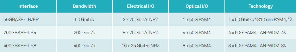
The performance of transmitters and receivers on optical interfaces of 50GE PAM4 optical transceivers must comply with the IEEE 802.3bs and IEEE 802.3cd standards.
An optical transceiver provides N 25Gbps electrical interfaces. For a 50GE optical transceiver, the two electrical lanes transmit TX1/RX1 and TX2/RX2 signals specified in the SFF-8436_MSA standards. The performance of electrical interfaces must comply with the CEI-28G-VSR LAUI-2 standard.
The optical transceiver with a transmission rate of 50Gbps on a single wavelength supports 50GE, 200GE, and 400GE interfaces. The following table lists the parameters for the 50GE, 200GE, and 400GE technical solutions.
Technical Solutions
Optical Component and Drive Chip
50G PAM4 optical transceivers use mature 25Gbps optoelectronic chips to deliver cost-effective solutions. In 50GBASE-LR 10 km scenarios, uncooled Direct Modulated Laser (DML) Transmitter Optical Sub-Assemblies (TOSAs) with TO packaging are used. Such a solution features mature technologies, low costs, low power consumption, and easy mass production. The linear DML driver chip can convert input PAM4 voltage electric signals into current signals that can directly drive lasers. Such chips deliver a high bandwidth and output large drive current. Their maximum working rate can reach 28GBaud. At the receive end, Receiver Optical Sub-Assemblies (ROSAs) with TO packaging are used. 25Gbps pins and linear Trans-Impedance Amplifier (TIA) chips are integrated to the ROSAs.

Optical components in 50GBASE-LR scenarios
In 50GBASE-ER 40 km scenarios, 25Gbps Electro-absorption Modulated Laser (EML) TOSAs with BOX packaging are used. External cavity modulated Distribution Feed-Back (DFB) lasers, isolators, monitoring diodes, thermistors, and EML components are integrated to the TOSAs and driven by voltage signals. Such a solution features wide linear domains, high ER, high output optical power, and low TDECQ. Linear EML drive chips can amplify input PAM4 signals and output them to next EMLs. These chips provide a high bandwidth, a small jitter, an adjustable output gain, and a working rate up to 28GBaud. At the receive end, APD ROSAs with TO packaging are used. 25Gbps APDs and linear TIA chips are integrated into the ROSAs. Such ROSAs feature high sensitivity and apply to 40km long-distance transmission.

Optical components in 50GBASE-ER scenarios
PAM4 Chip
PAM4 codec chips perform conversion between NRZ signals and PAM4 signals inside transceivers. In the transmit direction, PAM4 chips shape, amplify, and convert two 25Gbps NRZ signals output by boards into one 25GBaud PAM4 signal. In the receive direction, PAM4 chips use the Analog to Digital Converter (ADC) and Digital Signal Processing (DSP) technology to decode the one 25GBaud signal to two 25Gbps NRZ signals.
Differences Between Solutions of NRZ and PAM4 Transceivers
The optical components and chips of PAM4 transceivers are very different from those of NRZ transceivers. The following table lists the differences between 50G QSFP28 LR and 25G SFP28 LR.

The main difference lies in laser drive chips, TIA chips, and data processing chips.
- Since PAM4 code has four types of level logic, the laser drive chips and TIA chips are capable of linear outputs. NRZ transceivers output signals in amplitude limiting mode.
- PAM4 transceivers use DSP to implement conversion between a 50G PAM4 signal and two 25Gbps NRZ signals. NRZ transceivers transmit data using Clock & Data Recovery (CDR) chips only.
Originally article: https://www.gigalight.com/show-1137.html
Posted by: datacenternews at
03:28 AM
| No Comments
| Add Comment
Post contains 743 words, total size 8 kb.
January 24, 2019
A significant portion of Data Center Interconnections (DCIs) and telecom router-to-router interconnections rely on simple ZR or 80km transceivers. The former is mostly based on 100Gbps per 100GHz ITU-T window C-band DWDM transceivers, while the latter is mostly 10G or 100G grey wavelength transceivers. In DWDM links, the laser wavelength is fixed to a specified grid, so that with DWDM Mux and Demux 80 or more wavelength channels can be transported through a single fiber. Grey wavelengths are not fixed to a grid and can be anywhere in the C-Band, limiting capacity to one channel per fiber. DCI links tend to use DWDM because they have to utilize the optical fiber bandwidth as much as possible due to the extremely high-volume traffic between data centers.
Another emerging 80km market is the Multi-System Operator (MSO) or the CATV optical access networks. This need emerges because MSOs are running out of their access optical fibers and they need a transmission technology which would allow them to grow to a very large capacity by using the remaining fibers. For this reason they need to use DWDM wavelengths to pack more channels in a single fiber.
The majority of the 10G transceivers on 80km links will be replaced by 100G or 400G transceivers in the coming years. For that to happen, there are two modulation techniques to enable 80km 100G transceivers.
- 50G PAM4 with two wavelengths in a 100G transceiver
- Coherent 100G dual-polarization Quadrature Phase Shifted Keying (DP-QPSK)
Generally speaking, PAM4 is a low-cost solution but require active optical dispersion compensation (which could be a big headache as well as extra expense to data center operators) and extra optical amplification to compensate for the dispersion compensators. By contrast, Coherent approaches do not need any dispersion compensation and the price is coming down rapidly, especially when the same hardware can be configured to upgrade the transmission data rate per wavelength from 100G to 200G (by using DP-16QAM modulation).
When 400G per wavelength is needed in a DCI network within a 100GHz ITU-T window, coherent technology is the only cost-effective solution, because it will not be feasible for PAM4 to achieve the same high spectral efficiency of 4 bit/sec/Hz.
On the standards front, many standards organizations are adopting coherent technology for 80km transmission. The Optical Inter-networking Forum (OIF) will adopt coherent DP-16QAM modulation at up to 60Gbaud (400G per wavelength) in an implementation agreement on 400G ZR. This is initially for DCI applications with a transmission distance of more than 80km, and vendors may come up with various derivatives for longer transmission distances. Separately, CableLabs has published a specification document for 100G DP-QPSK coherent transmission over a distance of 80km aimed at MSO applications. In addition, IEEE802.3ct is in the process of adopting coherent technologies for 100G and 400G per wavelength transmissions over 80km.
As data rates increase from 100G to 400G and capacity requirements per fiber are driven by DCI needs, and assisted by volume driven cost reductions in coherent optics and in coherent DSPs, we expect coherent transmission to be the technology of choice for 80km links.
Posted by: datacenternews at
07:54 AM
| No Comments
| Add Comment
Post contains 523 words, total size 4 kb.
January 22, 2019
Since 2018, 100G high-speed optical transceivers have been deployed in large-scale data centers. The 100G QSFP28 series products are favored in large data center network architectures such as Microsoft, Google, and Facebook.
The 100G QSFP28 PSM4, 100G QSFP28 CWDM4, 100G QSFP28 LR4 optical transceiver is widely used in the construction of data center networks. It has won a large market share compared to other 100G optical transceivers. It can be said that it is a popular product in 100G high-speed optical transceivers. In general, if a product can be recognized by the market and widely used, the technical advantage must be the important reason.
Gigalight 100G PSM4, 100G CWDM4, 100G LR4 are using for data center. These products use technologies such as COB, WDM, mini TO and so on, which greatly reduced the cost, can save money for high-volume optical transceivers in the data center.
 100G PSM4
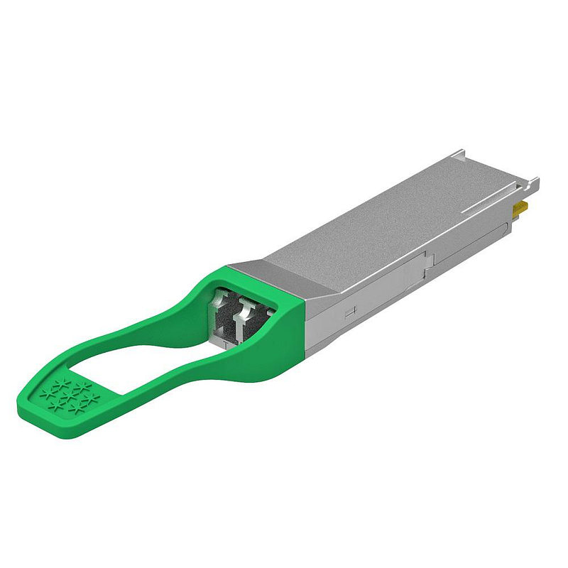 100G CWDM4
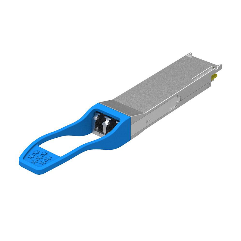 100G LR4
Automated Production and Chip-On-Board(COB) Packaging Technology
The chip-on-board package technology is an illuminant in which multiple of LED chips are integrally packaged on the same substrate.
Gigalight 100G QSFP28 PSM4, 100G QSFP28 CWDM4, 100G QSFP28 LR4 optical transceivers use automated production line and COB technology, greatly reducing cost and product power consumption.
WDM technology
In addition to COB technology, Gigalight 100G QSFP28 CWDM4 and 100G QSFP28 LR4 optical transceivers all introduce WDM technology. In optical transmission networks, WDM technology is considered to be an effective means to expand the transmission capacity of existing optical networks. It can increase the optical signal transmission capacity of existing optical fibers in the most cost-effective way, thus quickly meeting the increasing high bandwidth requirements of people. The most direct impact on life is that we go online, watch TV, make calls faster and more smoothly.
Wavelength Division Multiplexing (WDM) is a Multiplexer (Mux) that multiplexes optical carrier signals of different WDM wavelengths onto a single fiber for transmission at the transmitting end, and then uses a Demultiplexer(Demux) at the receiving end to transmit each the WDM wavelength separation technology, each WDM wavelength signal is independent of each other and is not affected by any transmission protocol and rate.
In addition, WDM technology enables bidirectional transmission of optical signals over a single fiber. This technology virtualizes one fiber into multiple fibers, which not only simplifies the structure of the optical transmission network, but also greatly saves fiber resources, thereby reducing the deployment cost of the optical network.

Using Mini TO Technology
Gigalight uses homemade Mini TO to effectively reduce costs and improve product reliability.
Conclusion
Through long-term technical accumulation, Gigalight self-developing optical devices, homemade TOSA/ROSA, gradually formed its own transmitting and receiving device packaging technology platform. The transmitter adopts the self-made mini TO plus AWG chip, and the receiving end adopts the COB packaging process, which greatly optimizes the product cost. In 2019, 100G optical transceivers will still occupy a mainstream position in data center deployment. In the new year, Gigalight will continue to optimize its production technology and will provide more high-quality 100G high-speed optical interconnect products for data centers.
Posted by: datacenternews at
07:49 AM
| No Comments
| Add Comment
Post contains 518 words, total size 5 kb.
30 queries taking 0.0408 seconds, 64 records returned.
Powered by Minx 1.1.6c-pink.

